
Resource
Retrofit bay sketch
One-bay sketch template for Line Integration Rail.
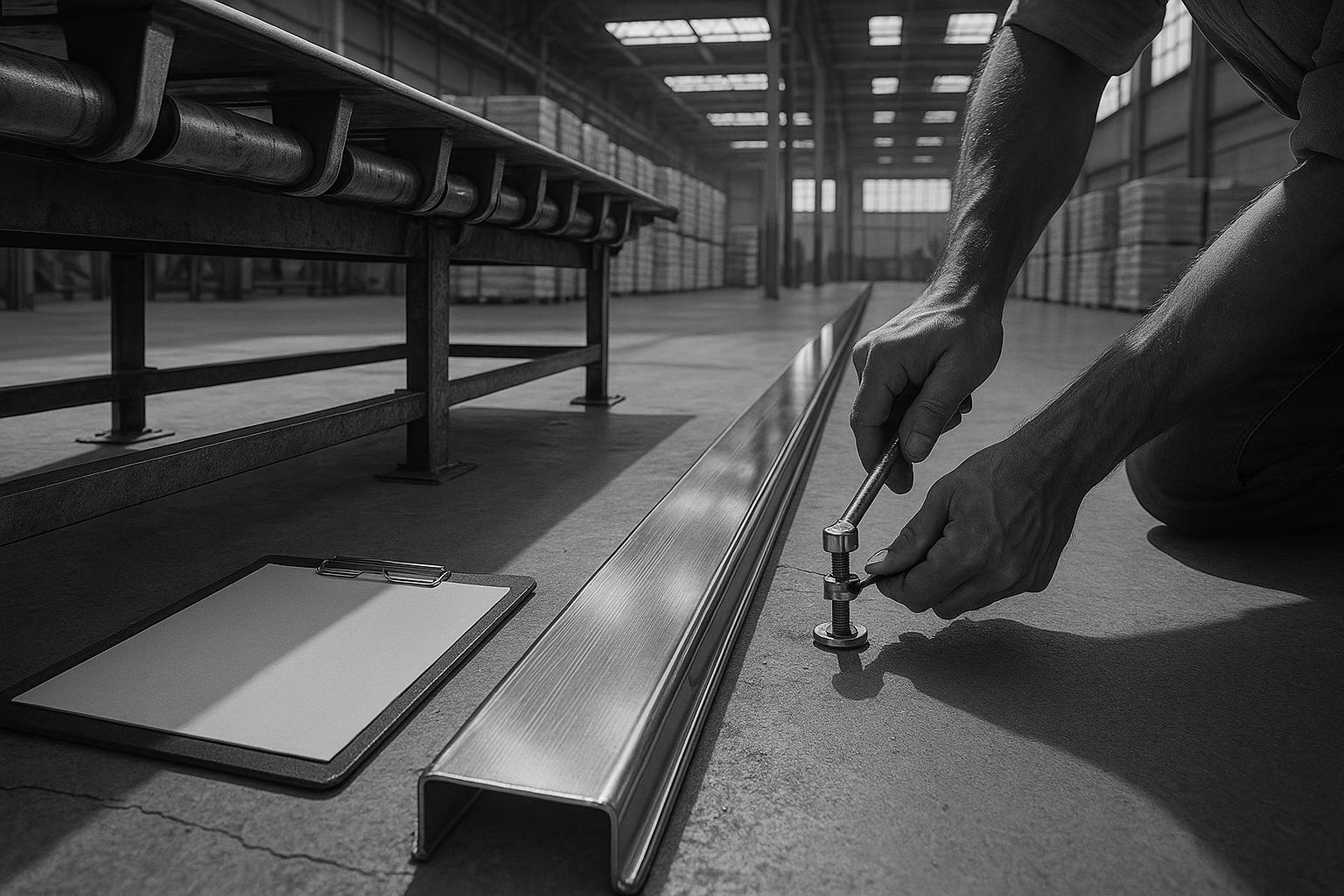
Retrofit bay sketch
The Retrofit Bay Sketch is a one-bay planning tool for fitting a Line Integration Rail to an existing bottling conveyor. Use it when one open section must carry sealing, capping, banding or inspection hardware. Plant managers use it for downtime planning, line setters for SKU change notes, and maintenance leads for brackets, guards, wiring and access checks before any cutting or drilling starts.
Start with the bay and pack details
Fill in the bay length first, from 1.5 m to 6 m, then mark bottle travel direction, conveyor width and belt centre. Add bottle diameter, neck size, cap height and bottle spacing at running speed. Write the pack family beside the sketch, such as 28, 33, 38 or 45 mm necks, so change parts stay clear.
Next, mark the infeed reference point, planned equipment position and discharge side. For foil sealing, show where the Seal Induction Pro sits in relation to the capper and sample check area. For tamper sleeves, mark sleeve placement and steam finish, then reference Band Shrink 120 so tray, hood and access space are planned together.
Add guides, sensors and reject space
Draw the guide rail faces after the pack notes. Mark the fixed side, then the adjustable side, with the opening for the widest bottle in the run. Put handwheel, clamp or tool access on the operator side. The setter must be able to reach adjustment points during changeover without stripping guarded parts from the conveyor.
Add each 24 V sensor point in bottle travel order. Show bracket side, cable exit and target bottle position. If a reject is needed, mark reject direction, pocket length, air line route and cleanout access. The sensor kit and reject pocket notes belong on the same sketch because timing, wiring and bottle removal share the same bay.
Worked example of a completed entry
A completed entry could read: Line 2, edible oil PET, 38 mm neck, 500 ml and 1 litre bottles, travel left to right, 2.4 m available, 180 mm conveyor width, operator side at the front. The sketch shows fixed guide at the back, adjustable guide at the front, sealing unit centred, entry sensor before it, check sensor after it, and front reject access.
For a torque retrofit, the same bay can show a Cap Torque Station instead of the sealer. The note must show the cap contact point, rail opening, operator adjustment side, guard edge and reject clearance. Maintenance can then see where brackets bolt on, where cables run, and which covers still lift for cleaning and belt tracking.
Common mistakes to catch early
The first mistake is drawing the bay from the wrong viewing side. Mark the operator side and travel arrow before anything else. Another mistake is measuring the outside of the guard and calling it usable conveyor space. Measure posts, hinges, drip trays and old brackets as they stand on the line, including guard swing and bin removal space.
Setters also miss bottle pitch after accumulation, especially where round packs surge into a narrow guide section. Record spacing during normal running, not only hand-fed trials. Maintenance teams often leave out cable routes, sensor bracket sides and wash access, which leads to exposed wiring or knocked sensors. Send the completed sketch, conveyor width, bottle spacing and neck size through our contact form, or bring the notes to the counter in Meadowdale Industrial, Germiston.